
Useful informations
YOU DO NOT KNOW? CHECK
-
Why use LED modules instead of incandescent light bulbs?
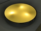
LED modules offer a much higher energy efficiency compared to regular and energy-saving light bulbs, and project a stronger luminous flux while reducing energy consumption. LED light sources may be additionally wired with e.g. dimmers or LED control units. Another of the many advantages of LED lights is illuminance uniformity, thus eliminating discomfort glare, which would appear in traditional light sources.
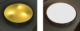
Three light bulbs (left) and an LED module (right) in an identical profile.
Moreover, the extended lifespan of LED lights, which may exceed 50 thousand hours, significantly reduces lighting system running costs. Regular light bulb lifespan is set at ca. 12-15 thousand hours.
-
What is LEDification?
It is an upgrade of old lamps, designed to work with traditional or halogen light bulbs, whereby the obsolete internal structures are removed and replaced with new LED modules and auxiliary electrical fittings.
LEDification in steps:
Old lamp Obsolete installations removed Mounting power supply
Fitting LED module LED module test Lamp assembly
-
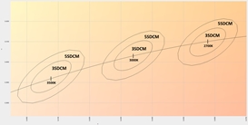
What is MacAdam ellipse?
It is impossible to produce LED lights with identical colour temperature. For those reasons, and some other ones, LED lights producers group products into so-called bins, i.e. sets comprising LED lights of similar parameters. Differences in colour between particular LED lights are described on the MacAdam ellipse. The said scale, depending on the area of the ellipse in question, is divided into tiers, or steps. Whenever a majority of people do not observe the just noticeable colour difference, such LED lights are matched to 1-step: MacAdam ellipse, or Standard Deviation Colour Matching (1SDCM). With increased colour difference discernible to observers, the number of steps also grows. At the same time the area of 2-step MacAdam ellpse (2SDCM) is twice the area of the 1-step ellipse, and so on. For 3000K LED lights, the colour difference may amount to ±30K at 1SDCM. In the case of 4SDCM, the said differences should be smaller than ±100K.
-
What is LED light binning?
Cutting-edge technology employed in the production of optoelectronic same-colour light sources will not prevent slight deviations in the parameters of such sources. Binning means grouping LED lights of highly similar parameters together. The intervals which form the basis for such LED light grouping are specified by any given manufacturer. Those could be ANSI binning standards, MacAdam or other.
-
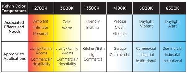
Which colour temperature to choose for you LED module?
The most common colour temperatures available on the market include 2700K, 3000K, 4000K, and 5000K. The best idea is to select LED modules in one of the colour temperatures above, which means they will be readily available and could be manufactured within the specification of the same or similar bin. The less frequently used LED lights comprise such colour temperatures as 2200K, 2400K, 3500K, 4500K, 5700K, and higher. Those light source colour temperatures may pose issues arising from limited availability, and prove significantly more expensive than standard LED lights. Still, choices of specific LED light colour temperatures should be determined by individual needs and preferences. It may be a good solution to choose Dynamic White modules, with tunable colour temperature. White light colour significantly affects one's well-being and successful colour choice is key to the most effective time use.
-
What's the difference between CC and CV modules?
With constant-current power supply, whatever the number of serial-connection LED modules, the current will always flow through the modules at the same value. The power supply output current will have a constant value, and the output voltage will adapt itself to the types of connected LED light sources. CC modules have no current stabilisers, and their lower rate of loss results from a single current regulation in the power supply. However, they may prove more problematic as the power supply will need replacing whenever LED lamp parameters are changed, or the lamps are reconfigured.
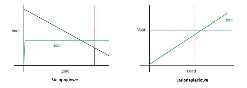
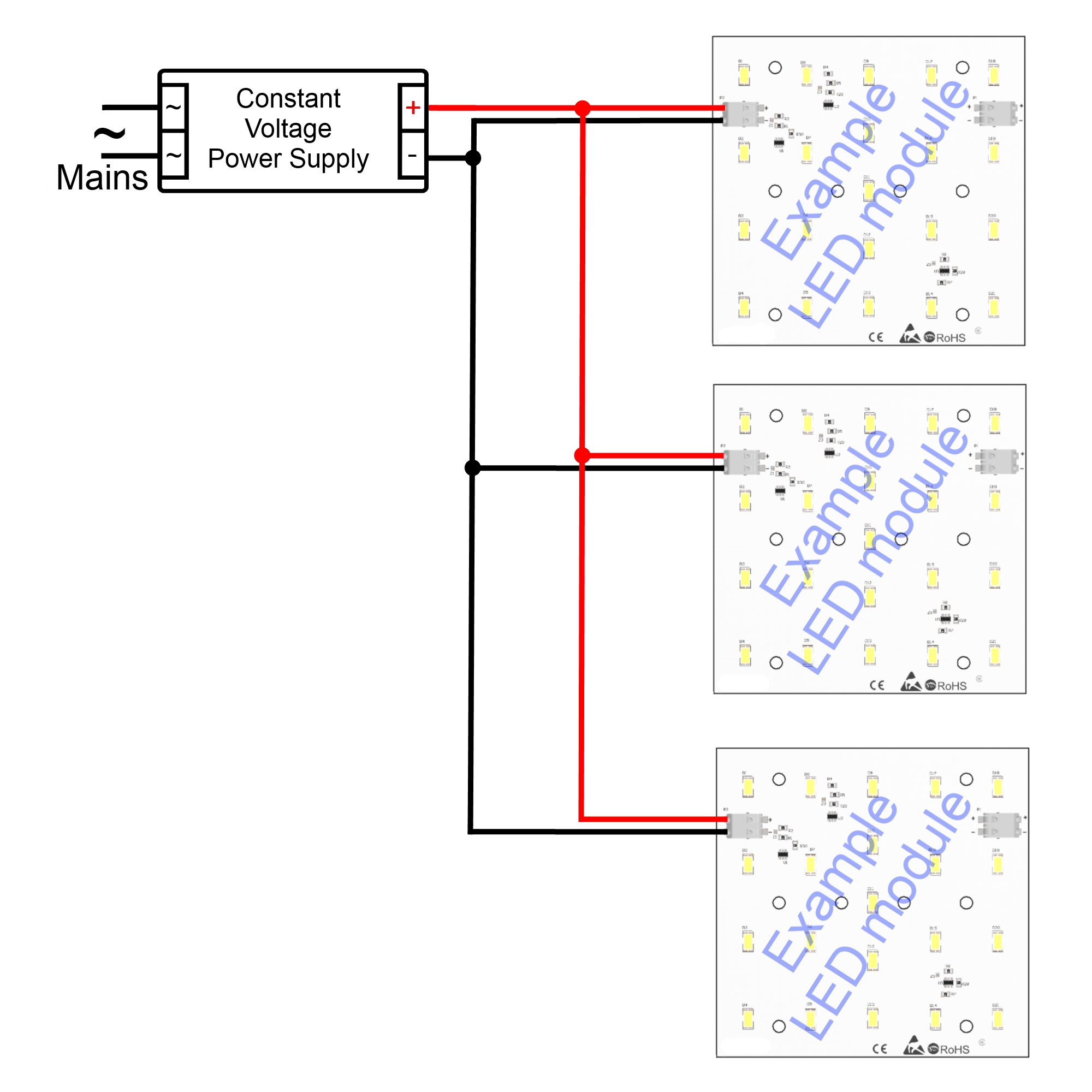
Constant-voltage power supply removes the limitation of uniform current supply to LED modules. That opens the way to connecting any number of LED light sources as long as their total power does not exceed the power of the supply. No need for replacing the power supply whenever the light fitting is reconfigured stands out as a major advantage of CV modules. Power supply output voltage remains constant, while energy consumption varies depending on the connected LED modules. This type of power supply makes LED lighting control easier and cheaper, yet voltage stabilisation in the supply unit and current stabilisation in LED modules translate into increased power losses compared to constant-current supply.
-
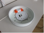
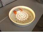
How to retrofit old lamps with LED modules?
As you have selected the right LED module and optional fittings, you are ready to embark on a LEDification adventure.
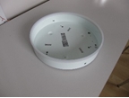
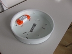
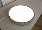
Before: After:

The first step is to remove all the elements in the lamp that you no longer need, then you can plan the layout for the new elements. Special magnets for mounting LED modules, LED control units, and power supply units, will ease your way to LEDifying obsolete lamps.
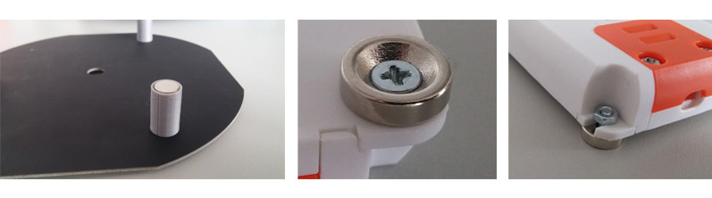
The power supply unit, LED control unit etc. may be mounted at the centre of the lamp, underneath the LED module. It is not always possible to do so as the LED module may be too close to the lens, thus resulting in light dispersion. The latter may manifest itself in observable bright circular or point defects. A solution to this may be to mount the power supply and LED control units by the side wall or outside the housing, and then the gap between the LED module and the lens should be correct. Successful LEDification means perfectly uniform illuminance across the entire area of the optical lens.
-
What is smart lighting?
Smart lighting is a novel technology for systems designed for high energy efficiency and user comfort. The technology offers state-of-the-art high-efficiency devices, and autonomous LED controls, which will dynamically fine-tune their parameters to the working conditions, number of persons in a room, daylight, etc. Controls will use wireless (e.g. Bluetooth, Zigbee, Thread, Lightify, IR) or wired communications (e.g. DMX, Dali, KNX/EiB, 1-10V), and an array of diverse sensors (e.g. HF, PIR). Smart lighting is all about modularity and ease of control reconfiguration. Such systems are mostly used for practical or aesthetic reasons, including special-purpose lighting, accent lighting, or general and utility lighting.
-
What types of controls are there?
There is a broad variety of LED control units available on the market, from key-switch dimmers, through non-mechanical touch-control dimmers, to no-touch proximity-sensor- or motion-sensor-based controls. LED lighting systems also use LED control units with radio-based controls and standards, including Dali, KNX/EiB, DMX, WiFi, Bluetooth, IR, etc. LED controls are likewise available as compact PCB-mounted smart modules.
-
What's the difference between RGB, RGBW, and RGBA modules?
RBG modules solely consist of red, green, and blue, or tricolour LED lights. Using such lights means they can produce almost any colour of the visible light spectrum. RGBW and RGBA LED modules have been fitted with additional LED lights. In RGBW modules those are mostly white LED lights with cold light temperature (ca. 5700K). Such lights boost white LED light intensity and offer a considerably improved colour rendering index (CRI) compared to RGB modules. The white light spectrum generated by those sources is highly selective. RGBA modules are additionally fitted with amber LED lights. Such modules generate LED light which boosts the saturation of other colours, thus rendering them more pastel-hued.
-
How temperatures affect the work of an LED module?
Working temperature affect the parameters of LED lights mounted on LED modules. Excessive temperatures on chips reduce LED light service life. That means that the light intensity decreases at a higher pace to reach the level of 80% or 70%, which is how LED light service life is defined by applicable norms. The time which elapses by the time the said intensity decreases to those levels is specified as L80, or L70 respectively. Heat sink- or radiator-based cooling systems may extend LED module service life. They may extend LED light service life by a factor of 2, 3, or even more, as long as the temperatures on the chips are maintained at adequately low levels. Additionally, increased temperatures have an adverse effect on a host of other LED light parameters, such as illuminance, energy efficiency, electrical resistivity, etc. The service life parameter for LED lights does not specify when the lights stop producing light entirely, but sets a time period by the end of which the luminous flux generated by the lights under predefined conditions decreases to a level prescribed by the norm.
-
How optical lenses affect LED light parameters?
Optical lenses are employed for a number of reasons, e.g. light concentration, light blurring, LED light protection, etc. by altering the optical parameters of LED module-generated light, using a variety of materials, shapes and so on. LED lamps use a range of e.g. milky, semi-clear, or transparent diffuser covers. Milky optical lenses disperse LED light much better than semi-clear, but such light is also more attenuated. Optical lenses materials aside, light parameters are also altered by employed lens shapes. The latter, by refracting light, may concentrate or disperse the luminous flux. Reflectors, whose surfaces turn light rays in a desired direction, may be used for concentrating light. Optical lens disadvantages include lowered: total illumination, luminous flux, efficiency, and half angle. At the design stage of LED lamps it is paramount to bear in mind to optimally fit LED modules, optic lenses, and special mounting holds. Incorrect selection of those elements results in poorer efficiency and may lead to non-uniform illuminance in LED light.
-
What are COB lights?
Chip on board (or COB) lights are LED lights comprising multiple chips encased under a single phosphorescent material. They key issue arising from such a solution is impeded heat dissipation. Further issues are posed by non-standard input current values in COB lights, and some difficulty in aligning light parameters with standard power supply or control units. It is more feasible to employ multiple medium- or high-power LED lights instead. Such LED modules radiate heat more readily, and may be made-to-measure to satisfy individual client needs and wishes. There is a broad range of COB equivalents available on the market, e.g. SCOB, or – for higher power applications – SKOT.
-
How optical lenses affect LED light parameters?
Optical lenses are employed for a number of reasons, e.g. light concentration, light blurring, LED light protection, etc. by altering the optical parameters of LED module-generated light, using a variety of materials, shapes and so on. LED lamps use a range of e.g. milky, semi-clear, or transparent diffuser covers. Milky optical lenses disperse LED light much better than semi-clear, but such light is also more attenuated. Optical lenses materials aside, light parameters are also altered by employed lens shapes. The latter, by refracting light, may concentrate or disperse the luminous flux. Reflectors, whose surfaces turn light rays in a desired direction, may be used for concentrating light. Optical lens disadvantages include lowered: total illumination, luminous flux, efficiency, and half angle. At the design stage of LED lamps it is paramount to bear in mind to optimally fit LED modules, optic lenses, and special mounting holds. Incorrect selection of those elements results in poorer efficiency and may lead to non-uniform illuminance in LED light.
-
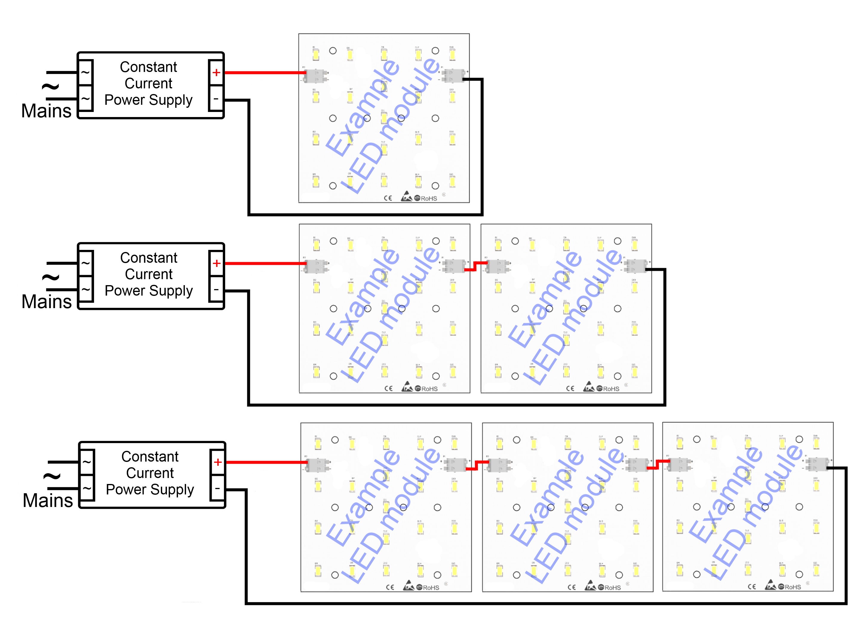
How to wire LED modules?
Building LED module-based circuits depends on module structure. As a rule however, CV LED modules and AC 230V modules must only be wired in parallel. Series wiring may result in damage or destruction of LED light sources. At the same time, CC LED modules should be wired in series, or in series-parallel – it is fundamental to ensure that each of the series entails an equal number of modules of identical parameters. CC and CV LED modules require LED power supply units, and – optionally – some additional LED control units. Any such devices must be dedicated to LED light applications. LED modules, and LED power supply and control units, must be wired in strict accordance with their polarity indications. Reverse polarity is particularly dangerous to DC-powered electronic devices.
A) B)
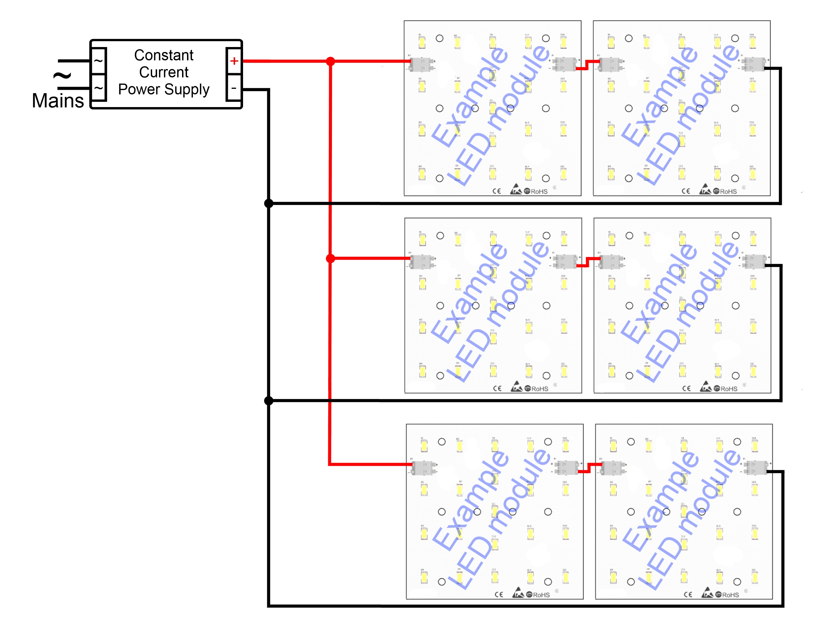
C) D)

A – CC modules wired in series; B – CC modules wired in series-parallel
C and D – CV modules wired in parallel
-
Which LED control unit should I use?
LED control units open the door to creating complex illuminations. When choosing LED control units, you should bear in mind the type and parameters of the LED modules you are planning to connect. The LED control unit maximum voltage and current must be higher than the combined maximum values of those necessary to ensure proper function of all the connected LED light sources. It is fundamental not to wire CC and CV LED modules, power supply units, LED control units, etc., as they are not compatible with one another. RGBW modules require LED control units fitted with four control channels. RGB, Dynamic White, and mono LED modules each need a single control channel fewer than the previously listed LED module. It is also possible to wire a few mono LED modules with LED control units fitted with a larger number of channels. For instance, a 4-channel LED control unit may effectively function as four dimmers. Broadly, the selection of control technology is determined by individual user needs. There is an abundance of wired and wireless systems from which to choose. The wired systems entail such control units as DMX, Dali, KNX/EiB, 1-10V, etc. For wireless transmissions LED control units use radiowave controls and a host of standards, including Zigbee, Thread, Lightify, IR, or Bluetooth. There are also LED control units fitted with external or built-in sensors, which detect e.g. motion, proximity, microwaves, lighting level etc. Those are mostly wired into smart lighting systems. It is recommended that you contact LED module producers to obtain information on compatibility with other products. Our sales advisers will be delighted to assist you in choosing a lighting system to fully satisfy all your requirements.
-
What's the difference between PCBs and MCPCBs?
Printed circuit boards (PCBs) are made from synthetic materials – mostly from FR4, a hard glass-reinforced epoxy laminate material. In comparison to other laminates, FR4 demonstrates significant resistance to high temperatures. It is also flame-resistant and self-extinguishing. PCPCBs are metal core printed circuit boards. The core is most frequently made from aluminium (in ALUPCBs) or copper (in COPPERPCBs). Such cores are highly efficient at dissipating excess heat or feeding it back to the heat sink. PCPCBs are perfect for high-power or AC 230V LED modules, but those are more complicated in production, and also more expensive.
-
How do Dynamic White modules work?
As they are fitted with white LED lights at the two extremes of colour temperatures, Dynamic White LED modules may be tuned to change their shade of white light. The first set of LED lights generates cold-white (CW) light whereas the other one produces warm-white (WW) light. The actual light colour temperature is the resultant of the two. Tuning the duty cycle of LED lights at the two extremes of colour temperature enables users to change the colour of the white light within the range of the said two extremes. Boosting the duty cycle for the CW channel, and reducing it for the WW one, results in a colder shade of the white LED light. Warming up the colour temperature is a reverse process. As the total power supply must remain at a constant, LED Dynamic White modules require a special LED control unit.
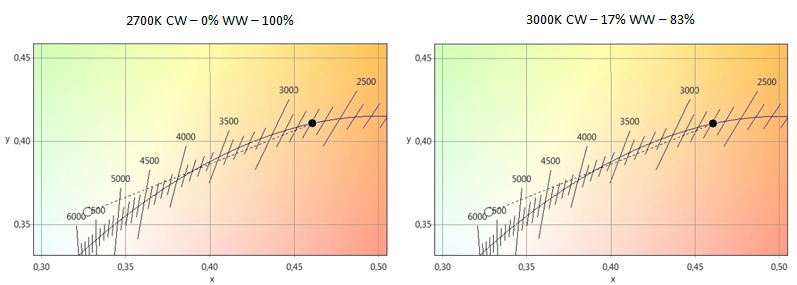

The above characteristics demonstrate the resultant colour temperature (the black point) across a range of settings for specific channel duty cycles.
-
What's the difference between popular LED equivalents and the more professional LED modules?
A large proportion of the LED equivalents available on the popular market is produced from cheap and poor-quality LED lights, with low energy efficiency and colour rendering index (CRI) found as low as under 60. Such CRI values distort colour perception, and may cause discomfort in persons or have adverse effects on human eyesight. What is more, popular-market LED equivalents often have built-in converters of simplistic design. Using such arrays may lead to short-circuiting and reduces the service life of such LED equivalents. They may also be prone to producing the detrimental pulsing light effect. Unlike popular LED lights, professional LED modules use high-quality LED lights with high values of colour rendering index (over 80), and high energy efficiency, which means such LED modules produce more and higher-quality light at the same nominal output, and less energy is converted into heat. State-of-the-art lights aside, professional LED light sources are designed with dedicated stabilising arrays. Plug-in LED modules are fitted with highly-efficient AC/DC converters whereas CV modules are fitted with current stabilisers with efficiency peaking at 130 lumens/W.
-
How about LED and health safety?
LED light sources used as recommended pose no health hazards, yet LED equivalents with low CRI values may detrimentally affect one's well-being and perception of the surrounding area. That is why it is highly recommended that you use LED modules with CRI values above 80. Light flickering, in line with the current frequency at the mains, is an additional issue rife among popular LED equivalents. Whenever using such equivalents, it is paramount to double-check that no fast-rotating tools and machines, e.g. drills or lathes, are found at the site. If the light flickering frequency overlaps with the rotating frequency of the tools and machines, it may produce an illusion them being turned off. It is a particularly hazardous phenomenon.